The Arduino PWM is very useful for controlling things. We can control the brightness of an led, speed of a motor, direction of a Servo motor, and many other things using PWM.
In this Arduino PWM tutorial, you will learn about the Arduino PWM function and how to use Arduino PWM function to control the brightness of an LED. First, we will control the brightness of the LED using Arduino code, and then we will control it manually through a potentiometer.
What is PWM
Pulse Width Modulation or PWM, is a technique to generate an analog like signal within a digital pin.
Arduino digital pins generally use a square wave to control things. So it has only two states, high (5 V on Uno, 3.3 V on an MKR board) and low (0 volts).
In the PWM technique, a square wave is switched between on and off state at high frequency. The duration of ON time of a period is called the pulse width. We can simulate any voltage between 0v to 5v by changing the pulse width of a period. This switching between on and off state is so fast, that the output signal acts like a stable voltage level between 0V and 5V.
Before going further, let’s discuss some key terms related to PWM.
Period: It is the time required to complete a full cycle. The period of a PWM signal is inverse of the PWM frequency.
TON (On Time): It is the time when the signal remains high within a period of time.
TOFF (Off Time): It is the time when the signal remains low within a period of time.
Duty Cycle: It is the percentage of time when the signal was high during the time of a period.
In the image below, the green line represents a complete cycle. The duration of time of one cycle is called the period of a PWM frequency and it is inverse of the PWM frequency.
Arduino’s PWM frequency is about 500Hz. So the green lines would measure 2 milliseconds each. A 100% duty cycle would give you 5v output and a 25% duty cycle would give you 5v*25%=1.25v output. That’s how you can generate any voltage between 0v to 5v.
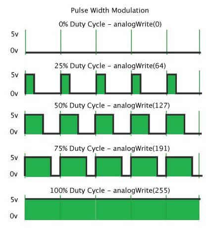
So how do you get a 50% or 20% duty cycle on Arduino code? for that, we will use Arduino’s analogWrite() function. analogWrite() works on a scale of 0 – 255. That means we can have 256 different voltages from 0v to 5v. And the difference between each step would be 5v/255 = 0.0196v.
So we can have voltages like 0v, 0.0196v, 0.0392v, …. 5v. It is almost like an analog signal.
So, analogWrite(0) gives a signal of 0% duty cycle i.e 0v output.analogWrite(50) gives a signal of ~ 20% duty cycle i.e 1v output.analogWrite(63) gives a signal of 25% duty cycle i.e 1.25v output.analogWrite(127) gives a signal of 50% duty cycle i.e 2.5v output.
Arduino Uno has six PWM pins, pin 3, 5, 6, 9, 10 and11. Pin 5 and 6 have a frequency of 980Hz and pins 3,9,10 and 11 have a frequency of 490Hz.
The frequency of the PWM signal on pins 5 and 6 is 980Hz. and on pin 3,9,10 and 11 it is 490Hz.
I think you got the basic idea of Arduino Pulse Width Modulation (PWM). Let’s look at some working examples to understand it even better.
Arduino PWM – LED Brightness Control
In this example, we will control the brightness of an LED using Arduino PWM. First, we will increase the analogWrite() value from 0 to 255 to gradually increase the voltage of the output pin from 0v to 5v. It will increase the brightness of the led from zero brightness to the fullest.
Then we will decrease the analogWrite() value from 255 to 0. Which will decrease the brightness of the LED from the fullest to the off state. Overall we will get a LED Dimming effect.
Circuit Diagram
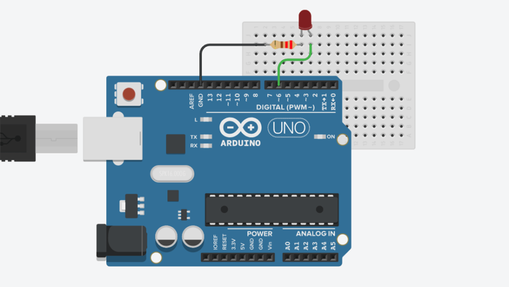
For this tutorial, you will need a similar circuit like LED blinking Arduino. First, you need to connect the long leg (+ve) of the LED to the Arduino pin no 6. Then connect the short leg (-ve) with a 220 ohm resistor and connect the other end of the resistor to the ground.
Code
const int ledPin = 6;
void setup() {
  // initialize ledPin (pin 6) as an output.
  pinMode(ledPin, OUTPUT);
}

// the loop function runs over and over again forever
void loop() {
  for (int brightness = 0; brightness < 255; brightness++) {
    analogWrite(ledPin, brightness);
    delay(2);
  }
  for (int brightness = 255; brightness >= 0; brightness--) {
    analogWrite(ledPin, brightness);
    delay(2);
  }
}
Explaining the code
Here you can see, we create a constant integer variable ledPin to hold the pin no we will use to control the LED. then in the setup() function, we set the ledPin as an output pin. In the loop() section, we create a for loop to increment the value of a variable brightness from 0 to 255. We pass that value to the analogWrite() function to increase the brightness of the LED. Then we use another for loop to decrease the brightness of the LED. We use a 2ms delay in both loops to slow down the process. You can increase or decrease the delay to slow down or speed up the process.
Manually control the Brightness of a LED
In this example, we will use a potentiometer to control the PWM value so that we can control the brightness of a LED manually.
Circuit Diagram
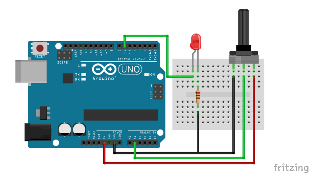
Here we use a 10k ohm potentiometer to control the brightness of the LED. Connect the two ends of the potentiometer to the Arduino 5v pin and ground pin. Then connect the middle pin of the potentiometer to analog input pin A1. The connection for the LED will remain the same as the previous circuit.
Code
int ledPin = 6;
int potPin = A1;
int potIn; // variable to store the value coming from the potentiometer
int brightness; // variable to hold the pwm value

void setup() {
  pinMode(ledPin, OUTPUT);
}

void loop() {
  //reading from potentiometer
  potIn = analogRead(potPin);
  //mapping the Values between 0 to 255
  brightness = map(potIn, 0, 1023, 0, 255);
  analogWrite(ledPin, brightness);
  delay(1);
}
Explaining the code
Here we create four integer variables to hold four different data. ledPin and potPin hold the pin number used to connect the LED and Potentiometer to the Arduino. potIn is used to hold the input value from the potentiometer and brightness is used to hold the PWM value.
In the setup section, we set the led pin as an output pin. Then in the loop section, we use analogRead() function to read from the potentiometer and pass that value to potIn using potIn = analogRead(potPin); this line.analogRead() reads from 0 to 1023 range where PWM works from 0 to 255 range. So we have to map the value from 0 to 1023 within 0 to 255. We can do this using the Arduino map() function like this brightness = map(potIn, 0, 1023, 0, 255);. We will hold that mapping value to the variable brightness and use it within an analogWrite() function to change the brightness. Use a small delay at the end of the loop to avoid fluctuation of input data.
Conclusion
In this tutorial, you have learned what is PWM and how it works with Arduino. You also learned how you can control the brightness of an LED using Arduino PWM. I hope you found this article useful and informative.
I would love to know how you will use Arduino PWM for your project. Use the comment section below to share your projects, thoughts, questions, and suggestions.
Comments might take up to 24 hours to be approved.

