The DHT11 sensor can measure temperature and humidity in the air. It gives pre-calibrated digital output, so you can interface with any microcontroller like Arduino, ESP32, Raspberry Pi, etc. You can easily use this sensor in your weather monitoring system, or home automation system.
In this tutorial, I will build a small circuit to interface a DHT11 humidity and temperature sensor with Arduino. Then I will show you how to print that data on an LCD as well as on an OLED display.
Table of Contents
- 1 DHT11 and DHT22 Humidity and Temperature Sensor
- 2 How DHT11 Measures Temperature and Humidity
- 3 Absolute Humidity vs Relative Humidity
- 4 How DHT11 Communicates with Arduino and Other MCUs
- 5 Pinout of DHT11 and DHT22
- 6 Connecting a DHT11 Sensor with Arduino
- 7 Arduino Code for DHT11 and DHT22
- 8 Display Humidity and Temperature on Serial Monitor
- 9 Use DHTlib Libreary to Read DHT11 Sensor Data
- 10 Display Humidity and Temperature on a LCD Display
- 11 Display Humidity and Temperature on a OLED Display
- 12 Conclusion
DHT11 and DHT22 Humidity and Temperature Sensor
DHT11 and DHT22 are the same types of sensors with some performance differences. Both use capacitive humidity sensors and thermistors to measure the relative humidity and temperature of the environment.
The DHT22 is more expensive, which means it is more capable than the DHT11. DHT22 can measure from -40 to +125 degrees Celsius with +-0.5 degrees accuracy, whereas the DHT11 can measure from 0 to 50 degrees Celsius with +-2 degrees accuracy.
Also, the DHT22 sensor has a better humidity sensor which can measure relative humidity from 0 to 100% with 2-5% accuracy, whereas the DHT11 can measure from 20 to 80% with 5% accuracy.
| DHT11 | DHT22 | |
| Temperature Range | 0 to 50 ºC | -40 to 80 ºC |
| Temperature Accuracy | +/-2 ºC | +/-0.5ºC |
| Humidity Range | 20% to 80% | 0% to 100% |
| Humidity Accuracy | +/-5% | +/-2% |
| Sampling Period | 1 Second | 1 Second |
How DHT11 Measures Temperature and Humidity
For sensing humidity, DHT11 has a resistive component that has two electrodes and a moisture-holding substrate between them. When the moisture-holding substrate absorbs the water vapor present in the air, it releases ions that increase the conductivity between two electrodes.
The change in resistance between two electrodes is inversely proportional to the relative humidity. When the humidity in the air increases the resistance between the electrodes is reduced and when the humidity decreases the resistance between electrodes is increased.
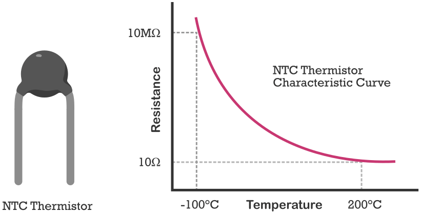
DHT11 also has an NTC Thermistor to measure temperature. A thermistor is a thermal resistor whose resistance is strongly dependent on temperature. The term “NTC” means “Negative Temperature Coefficient” which means its resistance decreases with increases in temperature.
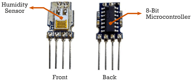
The sensor comes with a 14-pin, 8-bit microcontroller that converts the analog data from the humidity sensor and thermistor to digital values. It generates a digital signal that contains values of relative humidity, temperature, and a checksum byte.
Absolute Humidity vs Relative Humidity
The DHT11 or DHT22 can measure relative humidity only. So first you should know what is relative humidity and how to calculate relative humidity.
Absolute humidity is the total mass of water vapor present in a given volume or mass of air. It does not take temperature into consideration. On the other hand, relative humidity is the ratio of how much water vapor is in the air and how much water vapor the air could potentially contain at a given temperature.
The formula to calculate relative humidity is :

Where RH means – Relative Humidity,
ρw means – density of water vapor at a certain temperature, and
ρs means – the density of water vapor at saturation at that temperature.
The relative humidity is expressed as a percentage. 0% RH means the air is completely dry and at 100% RH condensation occurs.
How DHT11 Communicates with Arduino and Other MCUs
The DHT11 uses a one-wire protocol to communicate with Arduino and other MCUs. The sensor acts as a slave to a host controller. It will send digital data to the host controller when requested.
The communication between the host controller and DHT11 can be broken down into four steps.
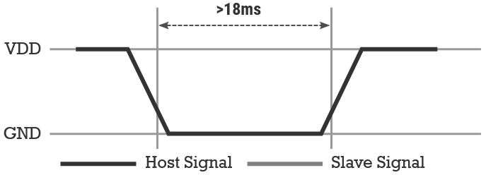
Request signal: To get the humidity and temperature data, the host must send a request signal for it. The data line is then pulled HIGH by default because of the pull-up resistor. The request signal is a logical LOW for 18 milliseconds followed by a low to high transition.
Then the host I/O needs to be set to input state to get the response signal.
Response: After receiving a request signal from the host, DHT11 sends a response signal to indicate that it is ready to transmit the sensor data. The response pulse is a logical LOW of 80 microseconds followed by a logical HIGH of 80 microseconds.

Data: After sending the response pulse, DHT11 begins to transmit sensor data containing the values of humidity, temperature, and a checksum byte. The size of the data packet is 40 bits or 5 bytes.
The first two bytes contain the values of relative humidity. The first byte contains the humidity integer data and the second byte contains the humidity decimal data.
The next two bytes (3rd and 4th) contain the temperature data. The third byte contains the integer part and the fourth byte contains the fractional part of the temperature.
The last byte is the checksum byte. This byte is used to check whether the received data is correct or not. If the binary sum of the humidity and temperature values (sum of the first four bytes) is equal to the checksum byte then the received data is correct.
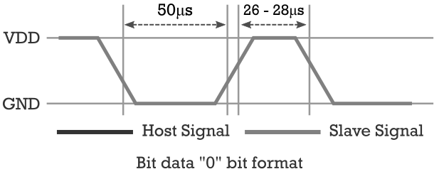
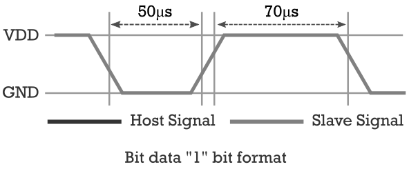
The bits are transmitted as a timing signal where the pulse width of the signal determines whether it is a bit 0 or bit 1.
Bit 0 starts with a 50 microseconds logic LOW followed by a 26-28 microsecond logic HIGH signal.
Bit 1 starts with a 50 microseconds logic LOW followed by a 70 microseconds logic HIGH signal.
End Signal: After transmitting the 40-bit data packet, the sensor sends a logic LOW signal for 50 microseconds and then pulls HIGH on the data pin. Then it goes into low power consumption sleep mode.
The data from the DHT11 sensor can be sampled at 1Hz or once every second.
Pinout of DHT11 and DHT22
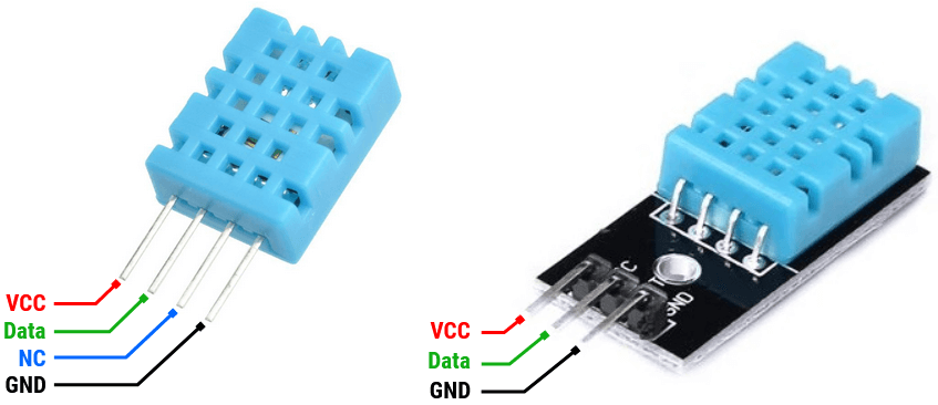
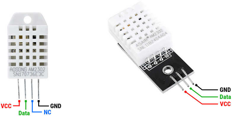
In the below image, you can see that both DHT11 and DHT22 have four pins. VCC, Data, No Connection, and Ground pin.
They also come with a PCB-mounted version which has three pins. VCC, Data, and Ground pin. This breakout board contains a pull-up resistor, which makes it easier to connect with the Arduino.
DHT11 Pinout
DHT22 Pinout
Connecting a DHT11 Sensor with Arduino
In this tutorial, I am using a DHT11 sensor and an Arduino Uno board. To connect the DHT11 with an Arduino board first, connect the DHT11 VCC pin to the Arduino 5v pin and the DHT11 ground pin to the Arduino ground pin.
Then connect the DHT11 data pin to any Arduino digital pin. Here I will use Arduino pin no 2. Now take a resistor of 5-10k ohm and connect the DHT11 data pin and Arduino 5v pin using this resistor. It makes a pull-up resistor configuration.
The following diagram shows you how to connect a DHT11 sensor with Arduino.
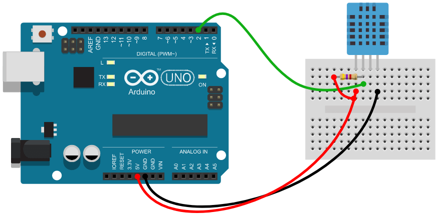
In the pinout section, you saw that DHT11 and DHT22 have similar pin configurations. So you can follow the same circuit diagram for DHT11 and DHT22.
One thing to note here is that the PCB version of these sensors has a built-in pull-up resistor. so you don’t need to connect an external resistor to it.
The following diagram shows you how to connect a DHT11 module with Arduino.
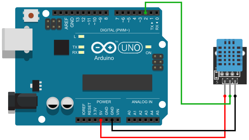
Arduino Code for DHT11 and DHT22
Writing a program to read the DHT11 sensor data is quite complex. But we have a few libraries like DHTlib and adafruit DHT library that will make it easier to read the DHT11 and DHT22 sensor data.
In this tutorial first I will show how to write Arduino code for DHT11 without a library. It is good to know how the library works behind the code. Then I will show how to use DHTlib to read DHT11 sensor data and print it on an LCD and OLED display.
Display Humidity and Temperature on Serial Monitor
In this section, I will show you how to read humidity and temperature data from a DHT11 sensor without using a library. I will print the binary humidity, temperature, and checksum byte data on the serial monitor so that you can understand the communication process between the MCU and the DHT11 sensor.
DHT11 Arduino Code without Library
#define DHT11_PIN   2

unsigned long TON_TIME = 0;
unsigned long TOFF_TIME = 0;

unsigned char data_byte[5];
unsigned int data_packet[40];
unsigned char bit_data = 0;
unsigned char checksum_byte = 0;
int bit_counter = 0;

void setup() {
  Serial.begin(9600);
  Serial.println("DHT11 Humidity & Temperature Sensor\n");
  delay(1000);//Wait before accessing Sensor
}

void loop() {
  pinMode(DHT11_PIN, OUTPUT);
  digitalWrite(DHT11_PIN, LOW);
  delay(18);
  digitalWrite(DHT11_PIN, HIGH);
  pinMode(DHT11_PIN, INPUT_PULLUP);

  TOFF_TIME = pulseIn(DHT11_PIN, LOW);
  if (TOFF_TIME <= 84 && TOFF_TIME >= 76) {
    while (1) {
      TON_TIME = pulseIn(DHT11_PIN, HIGH);
      if (TON_TIME <= 28 && TON_TIME >= 20) {
        bit_data = 0;
      }
      else if (TON_TIME <= 74 && TON_TIME >= 65) {
        bit_data = 1;
      }
      else if (bit_counter == 40) {
        break;
      }
      data_byte[bit_counter / 8] |= bit_data << (7 - (bit_counter % 8));
      data_packet[bit_counter] = bit_data;
      bit_counter++;
    }
  }
  checksum_byte = data_byte[0] + data_byte[1] + data_byte[2] + data_byte[3];

  if (checksum_byte == data_byte[4] && checksum_byte != 0) {
    Serial.println("Humidity: ");
    for (int c = 0; c <= 7; c++) {
      Serial.print(data_packet[c]);
    }
    Serial.print("\t");
    for (int c = 0; c <= 7; c++) {
      Serial.print(data_packet[c + 8]);
    }
    Serial.print("\t");
    Serial.print(data_byte[0]);
    Serial.print("%");
    Serial.println(" ");

    Serial.println("Temperature: ");
    for (int c = 0; c <= 7; c++) {
      Serial.print(data_packet[c + 16]);
    }
    Serial.print("\t");
    for (int c = 0; c <= 7; c++) {
      Serial.print(data_packet[c + 24]);
    }
    Serial.print("\t");
    Serial.print(data_byte[2]);
    Serial.print("C");
    Serial.println(" ");

    Serial.println("Checksum Byte: ");
    for (int c = 0; c <= 7; c++) {
      Serial.print(data_packet[c + 32]);
    }
    Serial.println(" ");
    Serial.print("CHECKSUM_OK");
    Serial.println("");
    Serial.println("");
  }

  bit_counter = 0;
  data_byte[0] = data_byte[1] = data_byte[2] = data_byte[3] = data_byte[4] = 0;
  delay(1000);
}
Upload the above code to the Arduino board and open the serial monitor. You will find output like this :
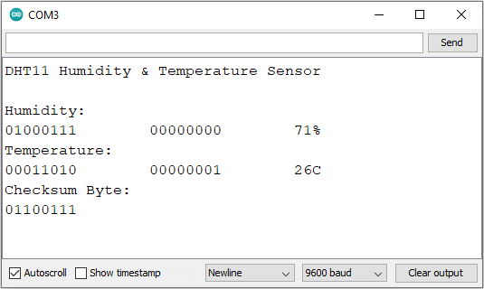
Explaining the Code
Here you can see that first, I created some variables to use in the program. I used DHT11_PIN to hold the Arduino PIN that is connected to the DHT11 data pin. TON_TIME and TOFF_TIME are used to measure the time duration of the HIGH pulse and LOW pulse respectively.
data_byte[] array is used to hold the humidity integer data, humidity decimal data, temperature integer data, temperature decimal data, and the checksum byte.data_packet[] is used to hold the 40-bit data packet coming from the DHT11 data pin. bit_data is used to read a single bit of data that comes from the DHT11 data pin. checksum_byte is used to store the calculated checksum byte. bit_counter is used to count 40 bits coming from the DHT11 data pin.
In the setup section, I initiate the serial communication at a 9600 bud rate. Then print the name of the project “DHT11 Humidity & Temperature Sensor”. Then I give 1 second delay before accessing the sensor.
In the loop section, I first send the start signal at the DHT11 data pin. That is a logical LOW for 18 milliseconds followed by a low to high transition.
pinMode(DHT11_PIN, OUTPUT);
digitalWrite(DHT11_PIN, LOW);
delay(18);
digitalWrite(DHT11_PIN, HIGH);
pinMode(DHT11_PIN, INPUT_PULLUP);
Then I check for the response pulse that is a logical LOW of 80 microseconds followed by a logical HIGH of 80 microseconds. To make the code simple I will only check for a logical LOW of 80 microseconds signal.
I will check for a logic LOW signal of length 76 to 84 microseconds so that it has some space for transmission error.
I am using the Arduino pulseIn() function to get the length of the pulse. pulseIn(pin, HIGH) returns the length of the pulse of a logic HIGH signal. and pulseIn(pin, LOW) returns the length of the pulse of a logic LOW signal. Know more about the pulseIn function from the Arduino pulseIn() reference page.
TOFF_TIME = pulseIn(DHT11_PIN, LOW);
if (TOFF_TIME <= 84 && TOFF_TIME >= 76) {
}
When we got a 26-28 microsecond logic HIGH signals, it is a bit 0.
if (TON_TIME <= 28 && TON_TIME >= 20) {
  bit_data = 0;
}
When we got a 70 microseconds logic HIGH signal, it is a bit 1.
else if (TON_TIME <= 74 && TON_TIME >= 65) {
  bit_data = 1;
}
The if-else loop will break when we got the 40-bit data from the DHT11.
else if (bit_counter == 40) {
  break;
}
I will use an array to store five parts of the data packet separately. In another array, I will put all the 40 bits of the data packet sequentially.
data_byte[bit_counter / 8] |= bit_data << (7 - (bit_counter % 8));
data_packet[bit_counter] = bit_data;
bit_counter++;
Then I will calculate the checksum byte.
checksum_byte = data_byte[0] + data_byte[1] + data_byte[2] + data_byte[3];If the calculated checksum byte is equal to the checksum byte received from the DHT11 sensor, then print the humidity, temperature, and checksum byte.
if (checksum_byte == data_byte[4] && checksum_byte != 0) {
}
In the end, I will reset the bit counter and set all the data bytes to 0. I will put 1 seconds delay before accessing the sensor again.
bit_counter = 0;
data_byte[0] = data_byte[1] = data_byte[2] = data_byte[3] = data_byte[4] = 0;
delay(1000);
Use DHTlib Libreary to Read DHT11 Sensor Data
In this section, I will show you how you can read the DHT11 sensor data using the DHTlib library.
To install the library first download it from the DHTlib Github repository. Then open the Arduino IDE, navigate to Sketch > Include Library > Add .ZIP Library, and select the DHTlib zip file that you just downloaded. That’s it now you can use the library in your program.
DHT11 Arduino Code to Show Sensor Data on Serial Monitor
#include <dht.h>
#define dht_pin 2 // DHT11 data pin connected to Arduino

dht DHT;

void setup() {
  Serial.begin(9600);
  Serial.println("DHT11 Humidity & Temperature Sensor\n");
  delay(1000);//Wait before accessing Sensor
}

void loop() {
  DHT.read11(dht_pin);
  int current_temp = DHT.temperature;
  int current_humi = DHT.humidity;

  Serial.print("Current Humidity = ");
  Serial.print(current_humi);
  Serial.print("%  ");
  Serial.print("Temperature = ");
  Serial.print(current_temp);
  Serial.print("C | ");
  Serial.print(current_temp * 1.8 + 32);
  Serial.println("F ");
  delay(2000);//Wait 2 seconds before accessing sensor again.
}
Upload the above code to the Arduino board and open the serial monitor, you will find the humidity and temperature data there.
Explaining the Code
You can see that I include the DHT library in the first line. Then I define the Arduino pin number that is connected to the DHT11 data pin. Then I create a dht object “DHT”.
In the setup section, I initiate the serial communication at 9600 baud and print “DHT11 Humidity & Temperature Sensor”. Then we give 1 seconds delay before accessing the sensor.
In the loop section, I am using the read11() function to read the data from the DHT11 sensor. If you are using the DHT22 sensor use the read22() function instead.
Then I use DHT.humidity and DHT.temperature to get the humidity and temperature values respectively. DHT.temperature will give the temperature values in Celsius. We can easily convert that celsius value to Fahrenheit using a simple formula: T(°F) = T(°C) × 1.8 + 32.
Now with the help of Serial.print() function, we can easily display the data on the serial monitor. After printing humidity and temperature data, I will give a 2 seconds delay before accessing the sensor again.
Display Humidity and Temperature on a LCD Display
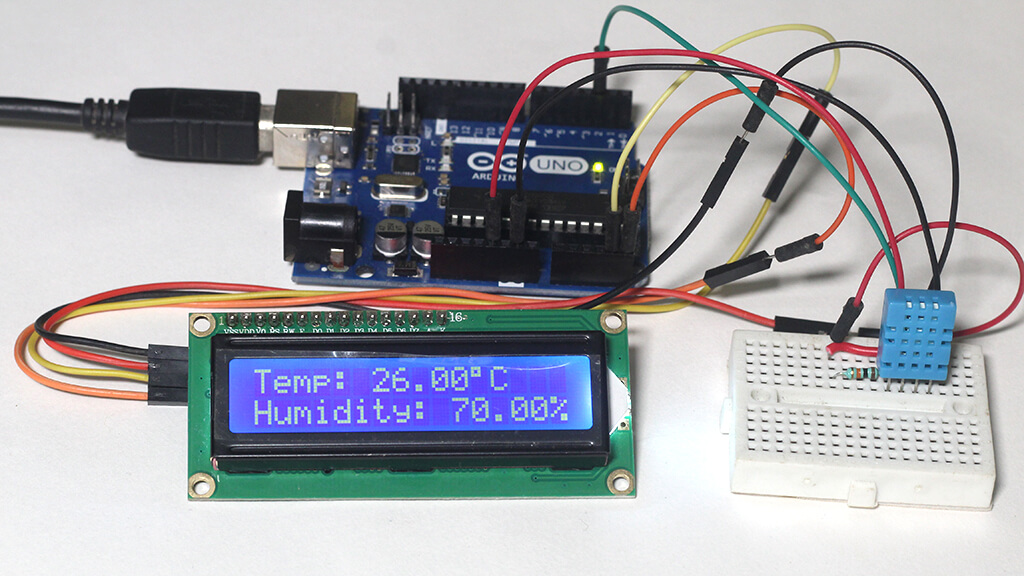
In this section, I will show you how to display DHT11 sensor data on an LCD Display. Here I am using a 16×2 I2C LCD display to show the sensor data.
If you don’t know how to connect an LCD to Arduino, read the below article :
Now take a look at the below circuit, you will find that the DHT11 sensor is connected to the Arduino as it was connected before. Now, you only need to connect the LCD to the Arduino board.
An I2C LCD display has only four pins: VCC, Ground, SCL, and SDA. Connect the LCDs VCC and Ground pin to Arduino’s 5v pin and Ground pin respectively. Then connect the SCL to Arduino A5 and SDA to Arduino A4 pin respectively.
DHT11 with Arduino and LCD Display Circuit Diagram
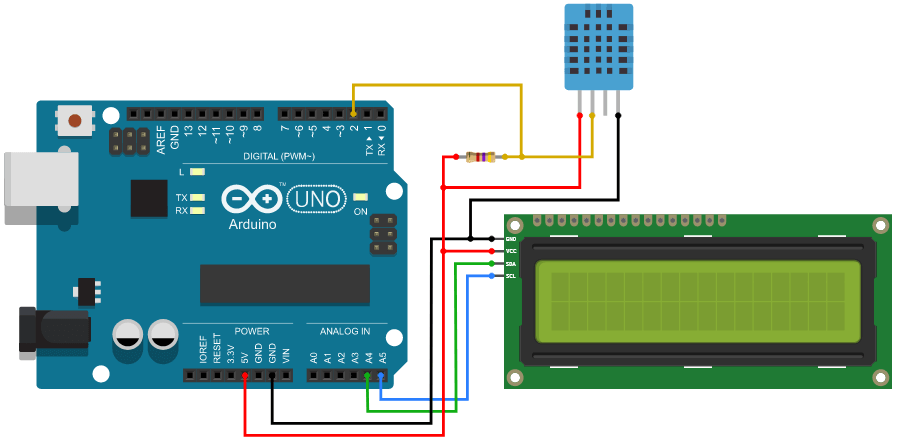
DHT11 Arduino Code for LCD Display
I have Installed the DHTlib library for the DHT11 sensor before. Now you need another library for the I2C LCD display – Arduino LiquidCrystal I2C Library. Download and install it like before.
Now upload the below code to your Arduino board. It will display the humidity and temperature data on the LCD display.
#include <dht.h>
#include <LiquidCrystal_I2C.h>

LiquidCrystal_I2C lcd(0x27, 16, 2);
dht DHT;

#define DHT11_PIN 2

void setup() {
  lcd.init();
  lcd.clear();
  lcd.backlight();      // Make sure backlight is on
}

void loop() {
  DHT.read11(DHT11_PIN);
  int current_temp = DHT.temperature;
  int current_humi = DHT.humidity;

  lcd.setCursor(0, 0);
  lcd.print("Temp: ");
  lcd.print(current_temp);
  lcd.print((char)223); //Shows degrees character
  lcd.print("C");
  lcd.setCursor(0, 1);
  lcd.print("Humidity: ");
  lcd.print(current_humi);
  lcd.print("%");
  delay(1000);
}
Explaining the Code
Here you can see that, I include the necessary library first. Then I create an I2C LCD object with the address 0x27 and a dht object. Then I define the Arduino pin number which is connected to the DHT11 data pin.
In the setup section, I first initialize the display then clear the display buffer, and turn on the backlight.
In the loop section, I use the read11() function to read the data from the DHT11 sensor. Then I use DHT.humidity and DHT.temperature function to get the humidity and temperature data respectively. Now you can easily print that data to the LCD using the setCursor() and print() function.
Display Humidity and Temperature on a OLED Display
In this section, I will show you how to display DHT11 sensor data on an OLED Display. Here I am using a 128×64 OLED display to show the DHT11 sensor data. If you don’t know how to connect an OLED display to Arduino, read my detailed guide on OLED display with Arduino.
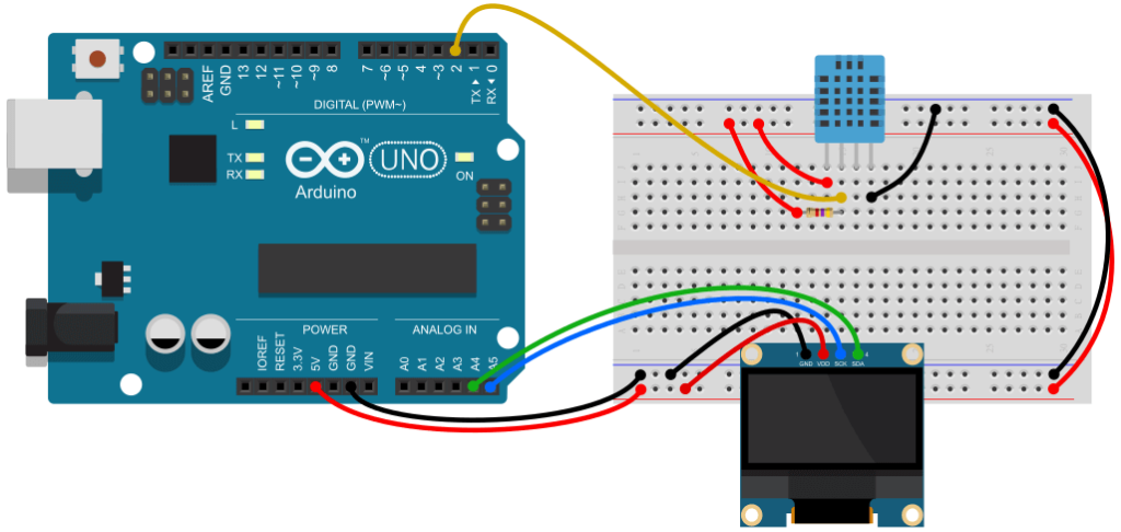
The below circuit shows you how to connect a DHT11 sensor and an OLED display to an Arduino board. Here you can see that I use a breadboard to make the connection simpler. The DHT11 sensor is connected to the Arduino Uno pin no 2 like before. Now you need to connect the OLED display to the Arduino board.
I2C OLED display has four pins: VCC, Ground, SCL, and SDA. Connect the OLEDs VCC and Ground pin to the +5v supply and Ground connection respectively. Then connect the SCL to Arduino A5 and SDA to Arduino A4 pin respectively.
DHT11 with Arduino and OLED Display Circuit Diagram
DHT11 Arduino Code for OLED Display
You have installed DHTLib before. Now you need to install Adafruit SSD1306 and Adafruit GFX library to control the OLED display. To install those libraries, go to Tools > Manage Libraries on your Arduino IDE and search for Adafruit SSD1306 and Adafruit GFX and install those. After installing successfully you can start writing code for it.
The below code will display the humidity and temperature data on the OLED display.
#include <dht.h>
#include <Wire.h>
#include <Adafruit_GFX.h>
#include <Adafruit_SSD1306.h>

dht DHT;
#define DHT11_PIN 2

#define SCREEN_WIDTH 128 // OLED display width, in pixels
#define SCREEN_HEIGHT 64 // OLED display height, in pixels

Adafruit_SSD1306 display(SCREEN_WIDTH, SCREEN_HEIGHT, &Wire, -1);

void setup() {
  display.begin(SSD1306_SWITCHCAPVCC, 0x3C);
  display.clearDisplay();

  display.setTextSize(2);
  display.setTextColor(WHITE);
}

void loop() {
  DHT.read11(DHT11_PIN);
  int current_temp = DHT.temperature;
  int current_humi = DHT.humidity;

  display.setCursor(0, 0);
  display.print("Temp:");
  display.print(current_temp);
  display.drawCircle(88, 3, 3, WHITE); // Print degree character
  display.setCursor(95, 0);
  display.print("C");

  display.setCursor(0, 31);
  display.print("Humi:");
  display.print(current_humi);
  display.print("%");
  display.display();
}
Explaining the Code
You can see that I include the necessary header file first. Then I create a dht object “DHT” and define the Arduino pin no that is connected to the DHT11 data pin. I also define the display height and width and create a display variable.
In the setup section, I initialize the display and clear the display buffer. Then I set the text size to 2 and text color to WHITE for the OLED display.
In the loop section, I first use the read11() function to read the data from the DHT11 sensor. Then I use DHT.humidity and DHT.temperature function to get the humidity and temperature values and store those values to current_temp and current_humi variable respectively.
I am using setCursor() function to set the cursor at a specific position and print() function to print text and variables.
Conclusion
I hope you learned a lot about DHT11 and DHT22 sensors and how to connect them with Arduino. If you like this tutorial please subscribe to our weekly newsletter to get more content like this.
Also, use the comment section below to share your ideas and projects related to DHT11 and DHT22.
