Arduino is a 5v (some are 3.3v) system, so we can easily control any 5v device using an Arduino output pin. But we cannot control high-voltage appliances directly with an Arduino, we need a relay for this. Relay is very helpful for controlling high voltage (120-240V) appliances like lights, fans, heaters, etc. using Arduino or other microcontrollers or low voltage circuits.
This article shows you how to control high-voltage appliances using an Arduino and a relay. I will discuss how a relay works and how to control a relay using Arduino. At the end of this tutorial, I will make a small project using an Arduino, relay module, and PIR sensor that activates a light whenever motion is detected in a room. Sounds interesting! Let’s build it together.
Table of Contents
What is Relay?
A relay is an electrical switch that is used to control high-voltage appliances using a low-voltage input signal. It can be paired with Arduino, ESP32, Raspberry Pi, or any other microcontroller, low-voltage device, and circuit to control a high-voltage appliance.
There are many types of relays available but electro-mechanical and solid-state relays work best with Arduino and other microcontrollers.
Electromechanical relay is very popular because of its low price. However, they can occasionally be noisy and less dependable. The presence of moving parts and the electromagnet within the relay can lead to inconsistencies and unreliability, especially in vibrating systems or high electromagnetic fields.
On the other hand solid state relay is built with semiconductor devices so no moving parts, thus making them silent and more reliable than electromechanical relay.
The below image shows a simple electromechanical relay.

How relay works
An electromagnetic relay contains an electromagnet and a moving contact. The electromagnet is energized using a low-voltage source. It can pull the moving contact to complete a high-voltage circuit and release the contact to break the circuit.
The below animation shows how an electromagnetic relay works.
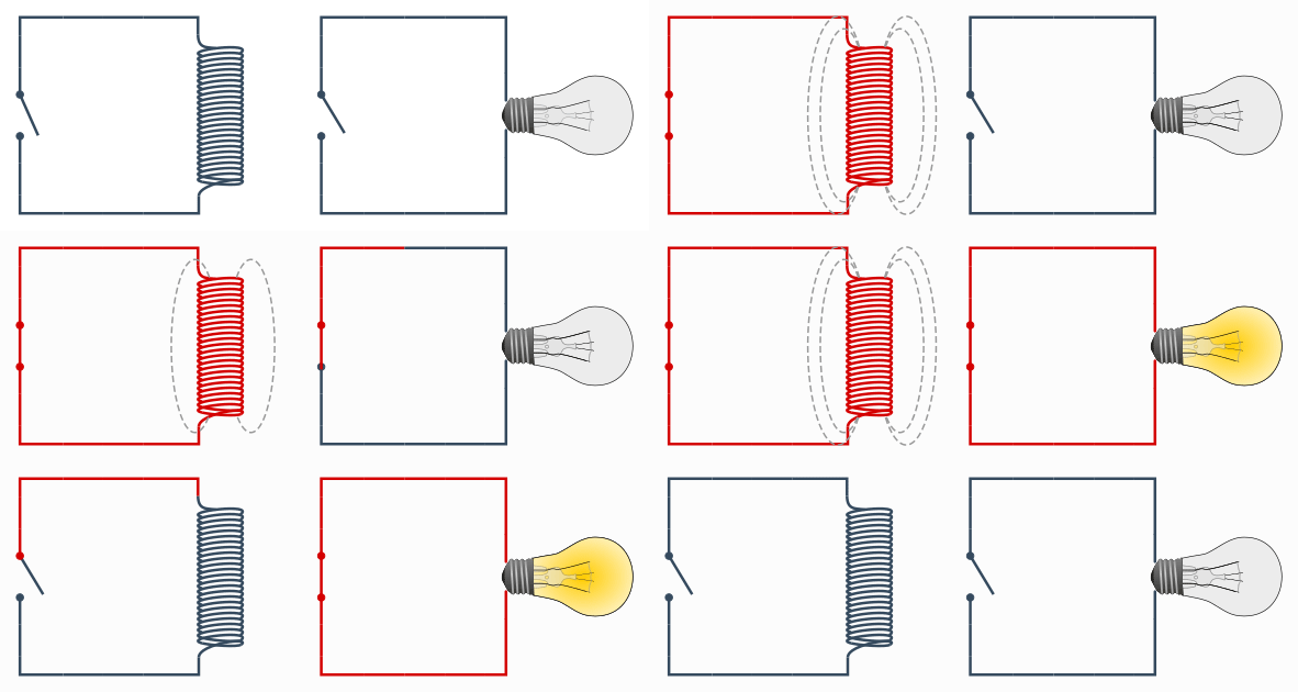
A relay requires a low voltage (e.g. 5v, 12v) to turn on the relay switch. You can use that switch to control high-voltage appliances. So we can control a relay (5v relay) switch using the Arduino output pin. On the other side, we can connect a high-voltage device (e.g. a 240v bulb) to control it.
Introduction to Relay Module
Since the relay is dealing with high-voltage appliances, flyback may occur in the circuit which leads to damaging your Arduino or microcontroller. To protect your low voltage control device/circuit we need a flyback voltage protection circuit.
A relay module contains all the essential protection circuits to safeguard the low-voltage control device. It has flyback diodes and optocouplers to limit the flyback current from flowing to the low-voltage circuit. So it is better to use a relay module instead of a simple relay for testing and developing a project.
The below image shows different components of a relay module.
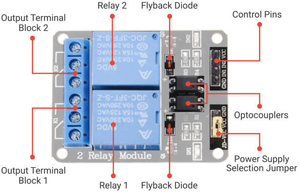
The relay module comes with different sets. A single-channel relay can handle only one appliance. So if you want to control multiple appliances go for a multi-channel relay. 1, 2, 4, 8, 16 channel relay is easily available.
Relay Module Pinout
The Relay Module has two terminals. Input terminal and output terminal. In the below image, the relay module has the input terminal on the right side and the output terminal on the left side.
On the input terminal, it has Ground, VCC, and Input pin. The number of input pins on a multichannel relay module is equal to the number of relays it contains.
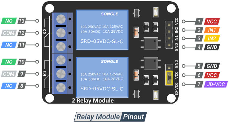
On the output side, it has three sockets for each relay – Common (COM), normally close (NC), and normally open (NO).
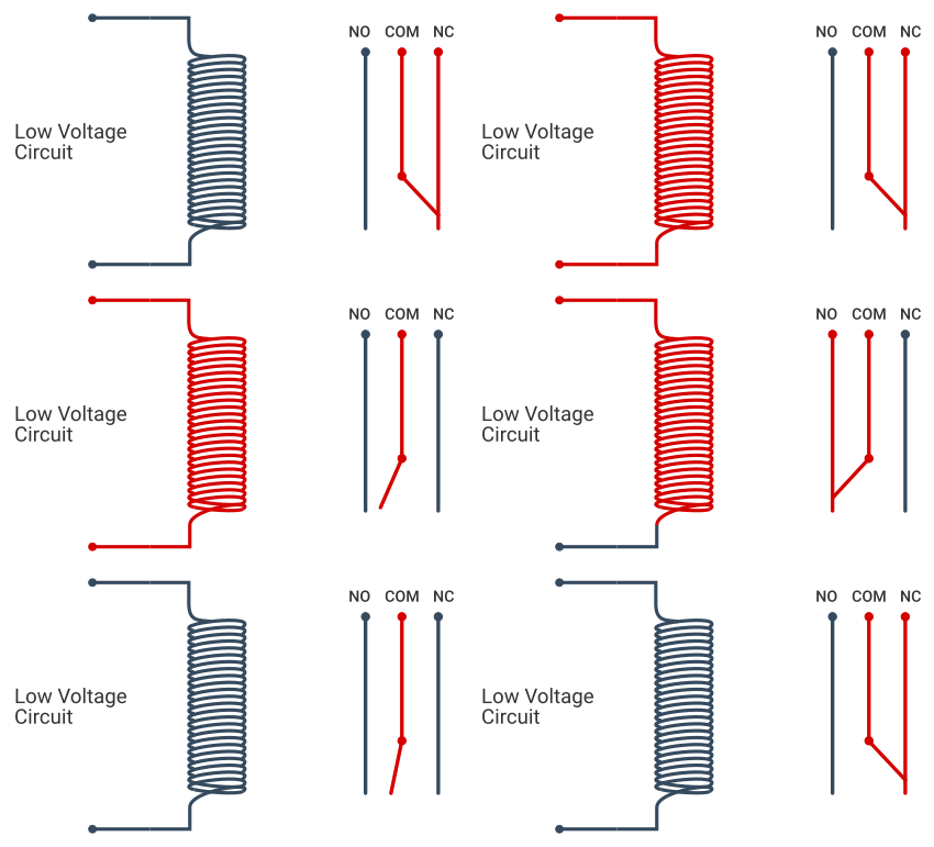
- COM: Common pin.
- NC (Normally Close): This pin is connected to the common pin by default. So if you use a COM pin and NC pin to connect to the bulb or other device, it will turn on by default. When the relay is triggered using the input signal the connection will break and your device will turn off.
- NO (Normally Open): On the other hand this pin is normally open. It will connect to the COM pin and complete a high-voltage circuit when the relay is triggered using the input signal. In this configuration, your device is normally off and the device will turn on when the relay is triggered.
In most cases, you don’t want your device to turn on by default so normally open connection is preferable.
The function of the common, NC, and NO pin could be understood easily using the below animation.
The relay module may also contain different sets of headers for different functions, typically containing power selection headers or input type selection headers.
Power Supply Selection Header
Within the power supply selection header, you will find three pins: GND, VCC, and JD-VCC. The JD-VCC pin provides power to the electromagnet of the relay.
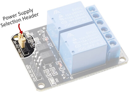
Initially, JD-VCC is connected to the VCC pin using a jumper cap, providing power to the electromagnet of the relay through the Arduino. In this setup, Arduino is not isolated from the relay switch, which means that if flyback occurs in the circuit, it can potentially damage the Arduino board. Additionally, if the relay module consists of multiple relays, it may draw excessive current beyond the Arduino’s limits, potentially resulting in damage to the Arduino boards.
Ideally, it is recommended to power the relay using an external power source. Nevertheless, for a simple project like controlling a bulb, it is acceptable to utilize the Arduino’s power to supply JD-VCC.
Input Type Selector Header
The input type selector header provides the option to choose between two input modes: High and Low level trigger. If the High-level trigger is selected, the relay will be triggered by a logic High signal. On the other hand, if the Low-level trigger is chosen, the relay will be triggered by a logic Low signal.
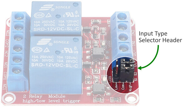
The header consists of three pins: High, Low, and common. By default, the common pin is connected to the High pin, indicating that the High-level trigger is selected. To opt for the Low-level trigger, simply connect the common pin to the Low pin.
Arduino Relay Circuit
You have learned enough about a relay module. Now it is time to connect it with an Arduino to control an electric bulb. Here, I will use an Arduino Uno board with a low-level trigger relay module to control a 220v electric bulb.
High Voltage Warning:Before we continue with this tutorial, I will warn you that this project involves high voltages. Incorrect or improper use could result in serious injuries or death. So please take all necessary precautions and turn off all the power supplies before working on the circuit. I take no responsibility for any of your actions. |
Working with high-voltage circuits could be dangerous, but you can minimize the potential risk by following the below points.
- Turn on the mains power supply only after uploading the code.
- Don’t touch any element connected to the circuit when the high voltage power supply is on.
- Turn off the mains power supply during any circuit work.
- Test the circuit with a low-voltage device (below 12v) before connecting it to the high voltage power supply.
Now coming to the circuit, you will notice that the circuit can be split into two sections. One section has a connection between the bulb and the relay module and the other section has a connection between the Arduino and the relay.
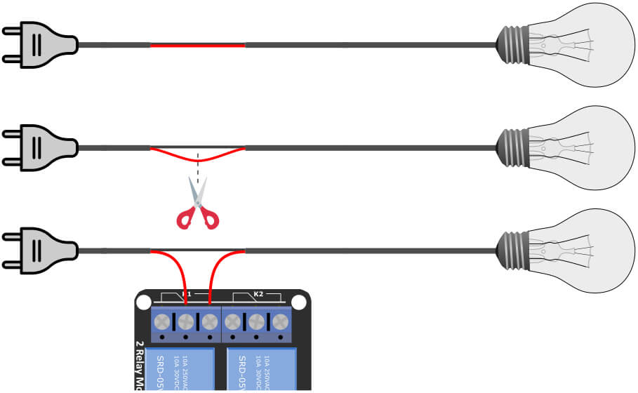
Let’s take a look at the first part. Look at the below image and follow the steps below. First, connect the bulb to the plug using two wires. Now take one of the wires and cut it. Connect one end to the COM pin and another end to the NO pin of the relay output terminal 1.
You have successfully connected the bulb with the relay but don’t put the plug into the socket at this point.
Now you have to connect the relay to the Arduino. First, connect the ground pin of the relay to the ground of the Arduino. Then connect the VCC pin of the relay to the 5v pin of the Arduino. Now connect the relay input pin 1 to the Arduino digital pin 2.
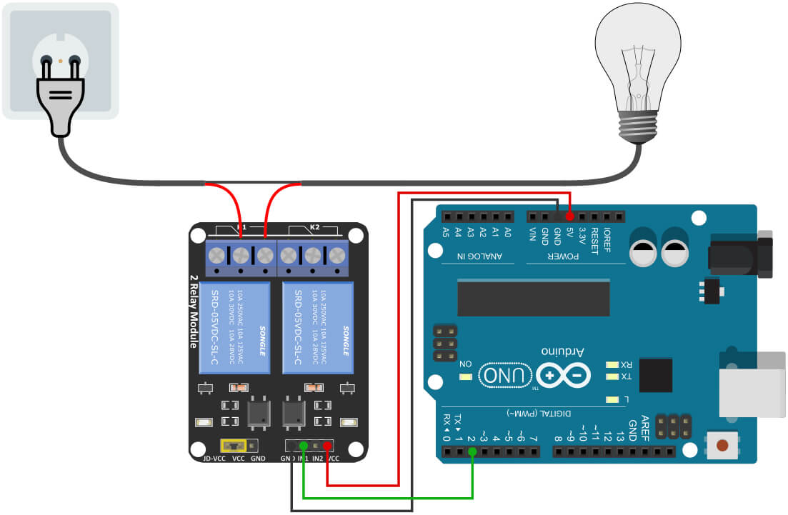
Here Arduino is getting power from the USB connection. You could also provide 7 to 12V (Volts) of DC to the Arduino’s barrel jack to power up the Arduino board. The JD-VCC pin is connected to the VCC pin using a jumper cap. This means the relay is taking power from the Arduino.
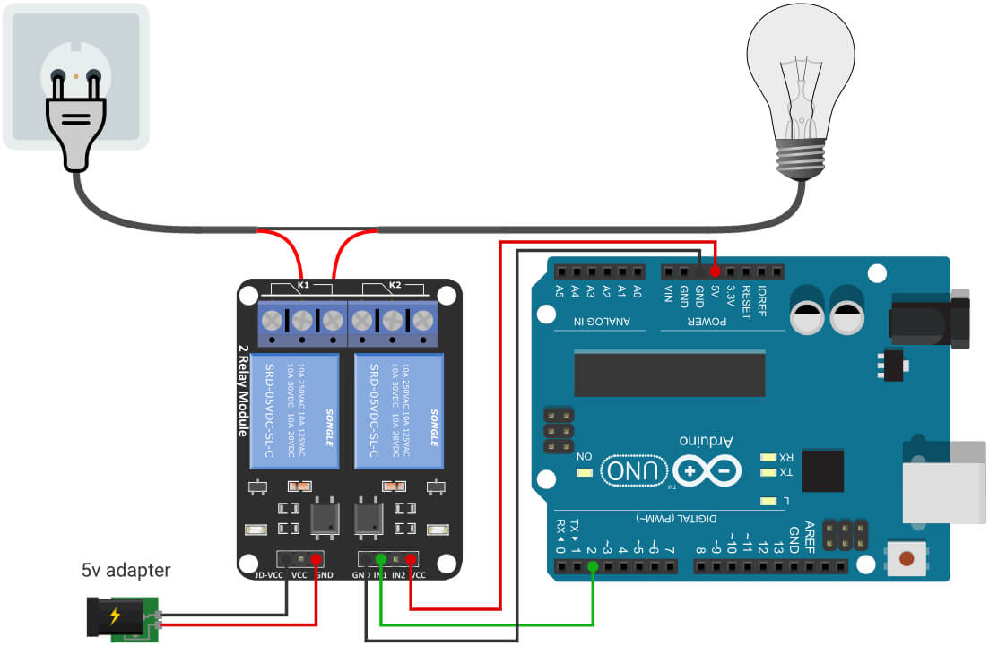
If you want to power the relay using an external power source, simply remove the jumper cap from the JD-VCC pin and connect it to the +ve terminal of a 5V power supply. Connect the ground pin to the ground of the 5V power supply.
Arduino Relay Code
Upload the below code, put the plug into the socket, and switch it on. You would see that the bulb will turn on for ½ second (500ms) and then turn off for 2 seconds (2000ms).
const int relayIN1 = 2;

void setup() {
  pinMode(relayIN1, OUTPUT);
}

void loop() {
  digitalWrite(relayIN1, HIGH);
  delay(2000);
  digitalWrite(relayIN1, LOW);
  delay(500);
}
The program is very simple, similar to the LED blinking program. First, we create a constant integer relayIN1 to hold the Arduino pin number that is connected to the relay. In the setup section, I set the relay pin as an output pin. In the loop section, I set the relay pin LOW for 500ms it will turn the relay on for 500ms (for LOW level trigger relay). Then I set the relay pin HIGH for 2000ms it will turn the relay off for 2000ms (2 seconds).
Motion Sensing Light with a Relay Module and PIR Motion Sensor
In this example project, we create a motion sensitive light. Here I have used a relay module, a PIR motion sensor, and a bulb to create a motion sensing light. The bulb lights up for 1 minute when it detects a motion.
If you are not familiar with the PIR motion sensor, you can read the below article.
It will be a very interesting project. So let’s get started.
Circuit Diagram
The relay module and the bulb are connected to the Arduino like before. We only have to add a PIR sensor to the Arduino board.
PIR sensor has three pins – VCC, GND, and Output pins. Connect the VCC pin to the Arduino 5v pin and GND to the Arduino ground pin. Connect the PIR output pin to the Arduino digital pin 3. You can use a breadboard to make the connections easier.
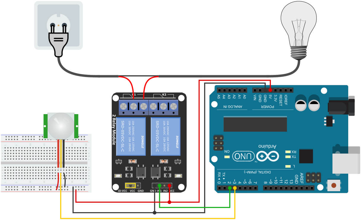
Arduino Code
Handling a PIR sensor is a little tricky. We can’t handle it like other sensors. For example, in the case of conventional sensors such as temperature or light sensors data can be periodically sampled at set intervals. A PIR sensor requires constant monitoring of its output pin to capture any motion events. Otherwise, we may miss an instance of motion.
In this project, I am using Arduino’s interrupt function for constant monitoring of the PIR sensor output pin.
const int relayPin = 2;
const int PIRInterrupt = 3;

volatile byte motion = false;

const long interval = 10000;
unsigned long lastTrigger = 0;

void setup() {
  // Set the relay pin as Output
  pinMode(relayPin, OUTPUT);
  digitalWrite(relayPin, HIGH);
  // PIRInterrupt pin set as an input
  pinMode(PIRInterrupt, INPUT);
  // Call the motionDetected function when a rising edge is detected
  attachInterrupt(digitalPinToInterrupt(PIRInterrupt), motionDetected, RISING);
}

void loop() {
  if ((millis() - lastTrigger) < interval && motion == true) {
    // during the interval period & motion = true
    digitalWrite(relayPin, LOW);
  }
  else {
    digitalWrite(relayPin, HIGH);
  }
}

void motionDetected() {
  lastTrigger = millis();
  motion = true;
}
Explaining the Code
First, I take two constant integer variables to hold the pin number that is connected to the relay and the PIR sensor.
const int relayPin = 2;
const int PIRInterrupt = 3;
A variable named motion is used as a flag in the program. Initially, I set it to false.
volatile byte motion = false;
I also need two other variables to handle the time. The interval is used to set the duration of how much time the bulb will remain on after a motion is detected. The lastTrigger is used to save the last time motion was detected.
const long interval = 10000;
unsigned long lastTrigger = 0;
In the setup() section, I set the relay pin as the output pin and turned it off by default. Here you can notice that the relay pin is set to HIGH to turn it off because I have a low-level trigger relay. It works with inverted logic – set the pin to LOW to turn the relay on and set the pin to HIGH to turn the relay off.
pinMode(relayPin, OUTPUT);
digitalWrite(relayPin, HIGH);
I set the PIR pin as an input pin.
pinMode(PIRInterrupt, INPUT);
Arduino’s interrupt function is used to continuously monitor the PIR pin. When a rising edge is detected on the interrupt pin (i.e. a motion is detected) it calls the motionDetected function.
attachInterrupt(digitalPinToInterrupt(PIRInterrupt), motionDetected, RISING);
In the motionDetected function, I simply record the last time a motion is detected and set the flag motion to true.
void motionDetected() {
  lastTrigger = millis();
  motion = true;
}
In the loop() section, I turn on the relay for 10 seconds if any motion is detected. For that, I will check if the difference between lastTrigger and the current time is less than the interval period (i.e. during the interval period) and if the motion is true then I will turn on the relay. Otherwise, I will turn it off.
void loop() {
  if ((millis() - lastTrigger) < interval && motion == true) {
    digitalWrite(relayPin, LOW);
  }
  else {
    digitalWrite(relayPin, HIGH);
  }
}


