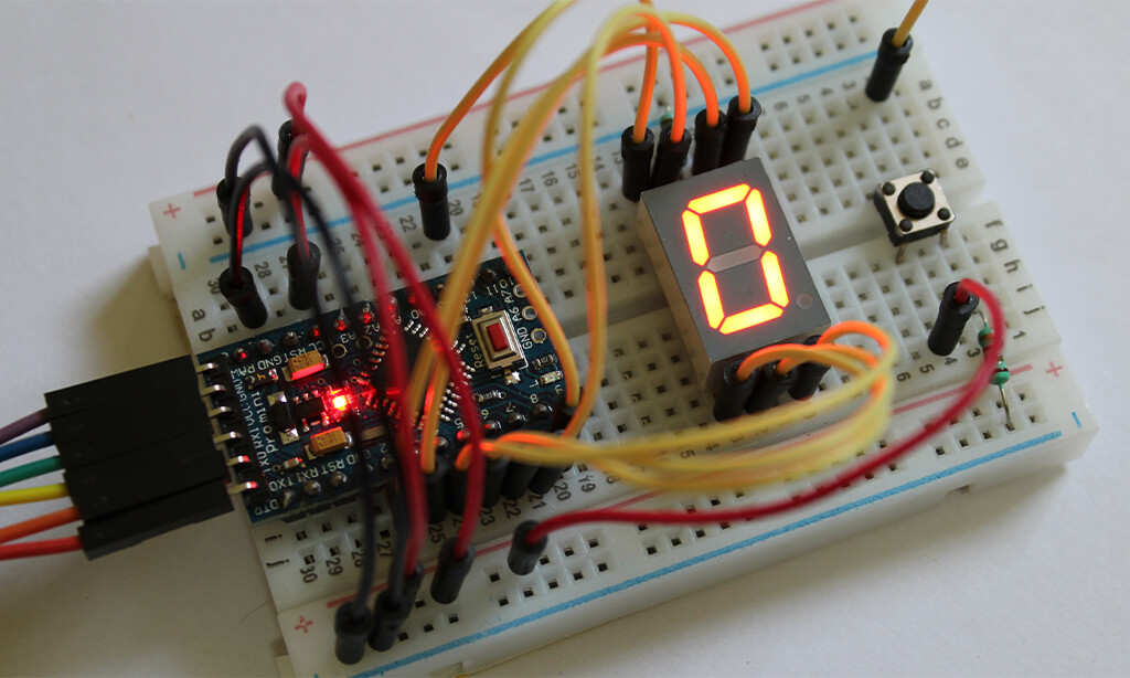
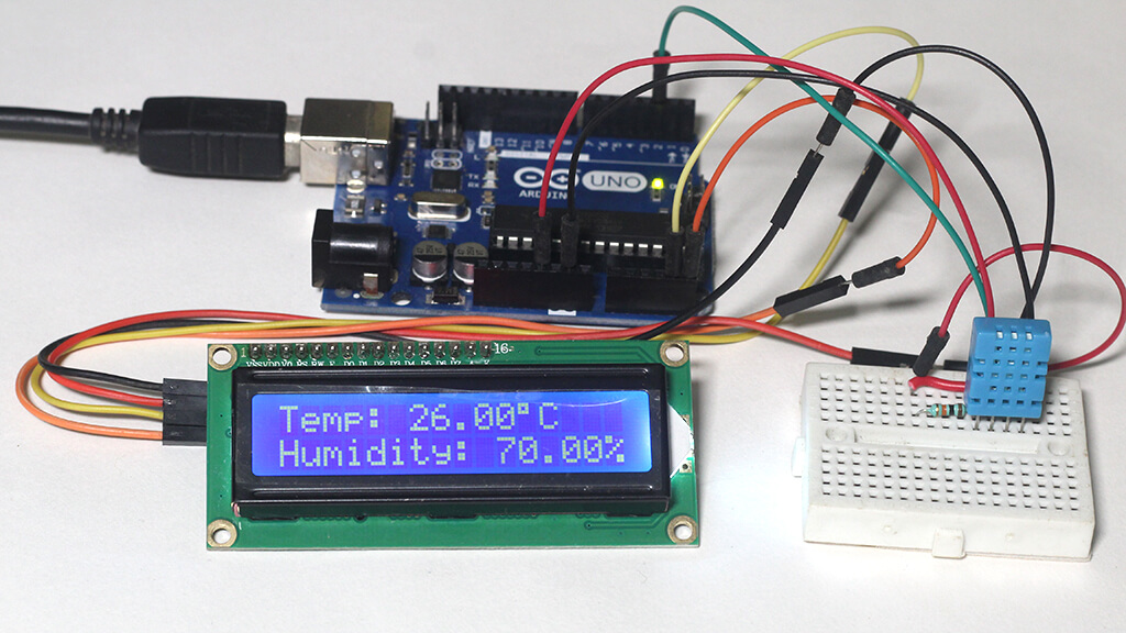
We use a variety of 7 segment displays in our day-to-day life. Such as a digital clock, stopwatch, micro oven, air conditioner, etc. It is a very simple and cost-effective way to display numbers like date, time, temperature data, etc. So if your Arduino project only needs to display numbers, consider using a 7 segment display.
Table of Contents
- 1 7 Segment Display
- 2 Connecting 7 Segment Display to the Arduino
- 3 How to Connect a Single Digit 7 Segment Display to Arduino
- 4 7 Segment Display Arduino Code
- 5 Arduino 7 Segment Display Testing
- 6 Print a Simple Number on 7 Segment Display
- 7 Arduino 7 Segment Display Counter
- 8 Arduino 7 Segment Display Rolling Dice
- 9 Summary
Seven segment display comes in different colors, digits, and sizes. Red, green, and blue are the most common and easily available displays. Some displays come with single-digit while two, three, four, and eight-digit displays are also available.
The picture below shows some typical 7 segment displays.
In this tutorial, we will learn how to Interface 7 Segment Display with Arduino with three examples. First, we will write a simple program to turn on all the segments one by one. Then we display a single number to the display. Then we create a counter that counts from 0 to 9 with a one-second interval.
7 Segment Display
7 segment display is nothing but an arrangement of seven LEDs in the shape of the number eight. Most of the 7 segment displays actually have eight LEDs with a dot on the bottom right of the digit. It serves as a decimal point.
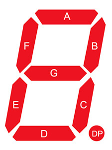
We mark all the LEDs to understand the 7 segment display better. We labeled the seven LEDs with A to G and the dot LED with DP. Each LED can be controlled separately so that we can form any number we want.
There are two types of 7 segment displays available: common cathode and common anode.
Common Cathode 7 Segment Display
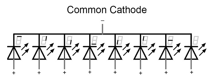
In a common cathode, all the cathodes of the LEDs are connected together with a single pin. So, we can put the common cathode to the ground.
If we put the common cathode to the ground, then we can easily control all the LEDs by turning the anode on and off.
Common Anode 7 Segment Display
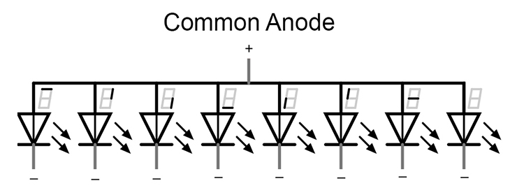
In a common anode display, all the anode of the LED is connected together with a single pin.
If we put the common anode to +5v, then a logic 0 (LOW) at the cathode turns the associated LED on and a logic 1 (HIGH) turns this LED off.
Connecting 7 Segment Display to the Arduino
A typical 7 segment display has 10 pins. Five on the top and five on the bottom.
If you have a common cathode display there will be two cathodes and eight anodes for eight segments. And if you have a common anode display there will be two anodes and eight cathodes for eight segments. Generally, a common cathode or common anode pin is in the middle of both sides.
Here is a pin diagram of a common cathode 7 segment display.
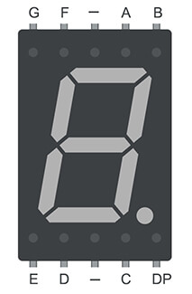
Before connecting the 7 segment display to the Arduino, you must know which display you have. Common cathode or common anode and which pin is connected to which segment of the display.
Know The Display type and Pin Orientation
Generally, the common cathode or common anode pin is in the middle of two sides. So first connect the ground pin to any of the middle pins of the display and insert the positive wire (red) into each of the other pins. If all the segments turn on one by one then it is a common cathode display.
If no segment is turned on then connect the positive wire (red) to any of the middle pins of the display and insert the ground wire (black) into each of the other pins. It must turn all the segments one by one. It is a common anode display.
How to Connect a Single Digit 7 Segment Display to Arduino
So you have figured out which display you have. If you have a common cathode display connect the common cathode pin to the Arduino ground pin. Connect the A, B, C, D, E, F, G, and DP to the Arduino digital pin 4, 5, 8, 7, 6, 3, 2, 9 respectively. Use the current limiting resistor in series with all eight anodes.
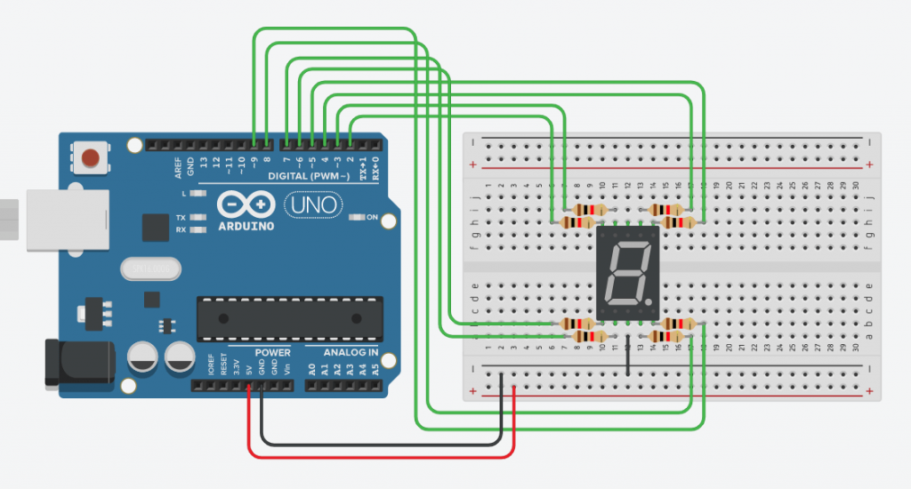
If you have a common anode display connect the common anode pin to the Arduino 5v pin. And connect the A, B, C, D, E, F, G, and DP to the Arduino digital pins 4, 5, 8, 7, 6, 3, 2, and 9 respectively. Use the current limiting resistor in series with all eight cathodes.
It is always advisable to use separate resistors in series for all eight LEDs to avoid them from burning. Resistor value depends upon the type of display. In our case, a 1k ohm resistor works fine.
7 Segment Display Arduino Code
Now it is time to write code for the seven segment display. I will give four examples to understand the code better.
In all the examples below we use a common cathode display. And connects all the segments using the table below.

Note:- You can use a popular library called SevSeg to control 7 segment displays. But I don’t recommend it to use for a small project. You should avoid using libraries for small projects to improve your coding skills.
Arduino 7 Segment Display Testing
Here we turn on all the eight segments one by one then turn them off to get familiar with how a seven segment display works.
Arduino Code
const int a = 4;
const int b = 5;
const int c = 8;
const int d = 7;
const int e = 6;
const int f = 3;
const int g = 2;
const int dp = 9;

void setup() {
  // Defining Pin Modes
  pinMode(a, OUTPUT);
  pinMode(b, OUTPUT);
  pinMode(c, OUTPUT);
  pinMode(d, OUTPUT);
  pinMode(e, OUTPUT);
  pinMode(f, OUTPUT);
  pinMode(g, OUTPUT);
  pinMode(dp, OUTPUT);
}

void loop() {
  // Turn on all the segment one by one
  digitalWrite(a, HIGH);
  delay(500);
  digitalWrite(b, HIGH);
  delay(500);
  digitalWrite(c, HIGH);
  delay(500);
  digitalWrite(d, HIGH);
  delay(500);
  digitalWrite(e, HIGH);
  delay(500);
  digitalWrite(f, HIGH);
  delay(500);
  digitalWrite(g, HIGH);
  delay(500);
  digitalWrite(dp, HIGH);
  delay(500);
  // Turn off all the segment at once
  digitalWrite(a, LOW);
  digitalWrite(b, LOW);
  digitalWrite(c, LOW);
  digitalWrite(d, LOW);
  digitalWrite(e, LOW);
  digitalWrite(f, LOW);
  digitalWrite(g, LOW);
  digitalWrite(dp, LOW);
  delay(500);
}
Here we first create eight constant integer variables to hold eight pin numbers connected to the Arduino. We can use those pin numbers directly to the program but if we use this way we can change the pin no easily if needed. Next in the setup() section, we set those pins as output pins. In the loop() section, we turn all the segments one by one with an interval of ½ sec and then turn them off all at once.
The above code is for beginners to understand better. But if you have some coding knowledge you can optimize the code like below. These two codes will give you the same results but when you have a complex project the second one will be very useful.
// array to store the pin no connected to A, B, C, D, E, F, G and DP
int seven_seg[] = {4, 5, 8, 7, 6, 3, 2, 9};
void setup() {
  // Defining pin modes
  for (int i = 0; i <= 8; i++) {
    pinMode(seven_seg[i], OUTPUT);
  }
}
void loop() {
  // Turn on all the segment one by one
  for (int i = 0; i <= 8; i++) {
    digitalWrite(seven_seg[i], HIGH);
    delay(500);
  }
  // Turn off all the segment at once
  for (int i = 0; i <= 8; i++) {
    digitalWrite(seven_seg[i], LOW);
  }
  delay(1000);
}
Here we first create an array to store the pin no. that is connected to A, B, C, D, E, F, G, and DP respectively. Next in the setup() section, we create a for loop to set those pins as output pins.
In the loop() section, we create two for loops. First for loop will turn all the segments one by one with an interval of ½ sec and the second for loop will turn them off all at once.
Print a Simple Number on 7 Segment Display
Here we print a simple number to the display.
Arduino Code
// array to store the pin no connected to A, B, C, D, E, F, G and DP
int seven_seg[] = {4, 5, 8, 7, 6, 3, 2, 9};

// array to create binary data map for ten digits (0 to 9)
int num_array[10][7] = {{ 1, 1, 1, 1, 1, 1, 0 },  // 0
                        { 0, 1, 1, 0, 0, 0, 0 },  // 1
                        { 1, 1, 0, 1, 1, 0, 1 },  // 2
                        { 1, 1, 1, 1, 0, 0, 1 },  // 3
                        { 0, 1, 1, 0, 0, 1, 1 },  // 4
                        { 1, 0, 1, 1, 0, 1, 1 },  // 5
                        { 1, 0, 1, 1, 1, 1, 1 },  // 6
                        { 1, 1, 1, 0, 0, 0, 0 },  // 7
                        { 1, 1, 1, 1, 1, 1, 1 },  // 8
                        { 1, 1, 1, 1, 0, 1, 1 }}; // 9

void setup() {

  for (int i = 0; i <= 8; i++) {
    // Defining pin modes
    pinMode(seven_seg[i], OUTPUT);
  }
}

void loop() {
  // print no 7 using the function created below
  printNumber(7);
}
// creating a function to print numbers
void printNumber(int number) {
  int pin;
  for (int j = 0; j < 7; j++) {
    pin = seven_seg[j];
    digitalWrite(pin, num_array[number][j]);
  }
}
First, we create an array to hold the pin no of Arduino. Then we create an array to create a binary data map for ten digits (0 to 9). In the setup() section, we set those eight pins as output pins. In the loop() section, we print the number 7 using printNumber() function. Then at the end, we define our function printNumber(). It will print any number (between 0 to 9) when we call the function properly.
Arduino 7 Segment Display Counter
Here we create a simple timer that counts from 0 to 9 with a one-second interval and reset to zero.
Arduino Code
// array to store the pin no connected to A, B, C, D, E, F, G and DP
int seven_seg[] = {4, 5, 8, 7, 6, 3, 2, 9};

int num_array[10][7] = {{ 1, 1, 1, 1, 1, 1, 0 },  // 0
                        { 0, 1, 1, 0, 0, 0, 0 },  // 1
                        { 1, 1, 0, 1, 1, 0, 1 },  // 2
                        { 1, 1, 1, 1, 0, 0, 1 },  // 3
                        { 0, 1, 1, 0, 0, 1, 1 },  // 4
                        { 1, 0, 1, 1, 0, 1, 1 },  // 5
                        { 1, 0, 1, 1, 1, 1, 1 },  // 6
                        { 1, 1, 1, 0, 0, 0, 0 },  // 7
                        { 1, 1, 1, 1, 1, 1, 1 },  // 8
                        { 1, 1, 1, 1, 0, 1, 1 }}; // 9

// define a function
void printNumber(int);

void setup() {
  for (int i = 0; i <= 8; i++) {
    pinMode(seven_seg[i], OUTPUT);
  }
}

void loop() {
  // creating a for loop which counts from 0 to 9
  for (int num = 0; num <=9; num++) {
    printNumber(num);
    delay(1000);
  }
}

// creating a function to print numbers
void printNumber(int number) {
  int pin;
  for (int j = 0; j < 7; j++) {
    pin = seven_seg[j];
    digitalWrite(pin, num_array[number][j]);
  }
}
The code is very simple and similar to the above code. Here we only need to create a variable whose value will increase from 0 to 9 and then go back to 0. We can easily achieve that using a simple for loop like this for (int num = 0; num <=9; num++). Then we pass the variable to our function like that printNumber(num) to print from 0 to 9. We use delay(1000) to create a 1s interval between two numbers.
Arduino 7 Segment Display Rolling Dice
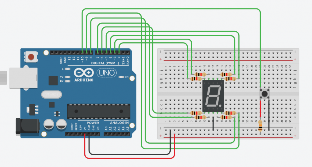
In this section, I will create a rolling dice. It gives us a random number between 0 to 6 when we press a button. if you are not familiar with the push button read the linked article – Arduino push button tutorial.
Circuit diagram
The circuit for this example will be almost the same as in example 1. You just need to add a push button to the Arduino like below. Here we will use pin no 12 to connect to the button.
Arduino Code
// create a constant integer to hold the button pin value
const int buttonPin = 10;

// array to store the pin no connected to A, B, C, D, E, F, G and DP
int seven_seg[] = {4, 5, 8, 7, 6, 3, 2, 9};

// array to create binary data map for ten digits (0 to 9)
int num_array[10][7] = {{ 1, 1, 1, 1, 1, 1, 0 },  // 0
                        { 0, 1, 1, 0, 0, 0, 0 },  // 1
                        { 1, 1, 0, 1, 1, 0, 1 },  // 2
                        { 1, 1, 1, 1, 0, 0, 1 },  // 3
                        { 0, 1, 1, 0, 0, 1, 1 },  // 4
                        { 1, 0, 1, 1, 0, 1, 1 },  // 5
                        { 1, 0, 1, 1, 1, 1, 1 },  // 6
                        { 1, 1, 1, 0, 0, 0, 0 },  // 7
                        { 1, 1, 1, 1, 1, 1, 1 },  // 8
                        { 1, 1, 1, 1, 0, 1, 1 }}; // 9

// variables will change:
int buttonState = 0;         // variable for reading the pushbutton status
int pushCounter = 0;         // counter for the number of button presses
int lastButtonState = 0;     // previous state of the button
long randNumber;

// define a function
void printNumber(int);

void setup() {
  for (int i = 0; i <= 8; i++) {
    // Defining pin modes
    pinMode(seven_seg[i], OUTPUT);
  }
}

void loop() {
    // read the state of the pushbutton value:
  buttonState = digitalRead(buttonPin);

  // compare the buttonState to its previous state
  if (buttonState != lastButtonState) {
    // if the state has changed, increment the counter
    if (buttonState == HIGH) {
       // print a random number from 0 to 6
  randNumber = random(0, 6);
  printNumber(randNumber);
    }
    // Delay a little bit to avoid bouncing
    delay(50);
  }

// save the current state as the last state, for next time through the loop
  lastButtonState = buttonState;
}
// creating a function to print numbers
void printNumber(int number) {
  int pin;
  for (int j = 0; j < 7; j++) {
    pin = seven_seg[j];
    digitalWrite(pin, num_array[number][j]);
  }
}
Here we use an Arduino function random() to generate a random number between 0 to 6. Then we print that number to the display using our printNumber() function.
Summary
In this tutorial, I have shown you how to connect a 7 segment display to Arduino and give four examples to understand it better. I hope you found it useful and informative.

